Know about Mechanical Seal in a Centrifugal Pump
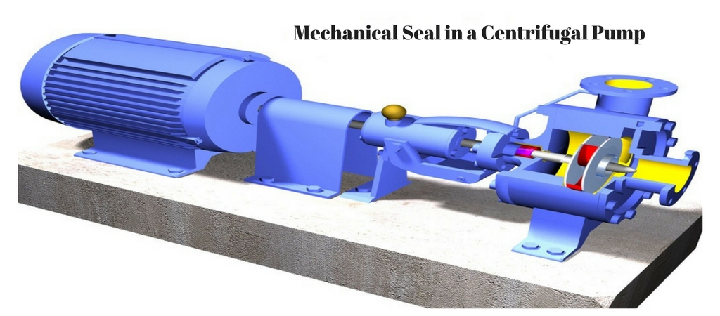
Mechanical Seal in a Centrifugal Pump – Mechanical seals are the new age sealing product replacing gland packing and old designs associated with it. They assist in sealing the rotating component of the shaft alongside the stationary component/part of centrifugal pump housing. They are used as devices that form the packing between the rotor and the stationary part of the centrifugal pump to prevent the leakage of the fluid being pushed by the pump.
They act as a check valve and a slider bearing. The clear function as a check valve is to put off liquid under pressure from leaking of the centrifugal pump, or from drawing air into the pump when there is vacuum surrounding.
The mechanical seal is used in a pump, mixer and other mechanical engineering scenarios to contain the fluid within a vessel where a shaft rotates through a stationary (or rotating) housing.
Basic Design of a Mechanical Seal
- The stationary part of the seal is fitted to the pump housing with a static seal, this may be sealed with an o-ring or gasket clamped between the stationary part and the pump housing. So sealing points in the seal design are straightforward and static seals.
- The rotary portion of the seal is conserved onto the shaft typically using an O ring. This sealing point can also be looked upon as static as this component of the seal rotates with the shaft. The mechanical seal itself is the interface between the static and rotary portions of the seal.
- One part of the seal, either to static or rotary portion, is always resiliently mounted and spring loaded to accommodate any small shaft deflections, shaft movement due to bearing tolerances and out-of-perpendicular alignment due to manufacturing tolerances.
Fluid Film
In mechanical seals the faces are being kept lubricated by having a thin film of fluid amid the seal faces. This film can either come from the process fluid being pumped or from an external source. With no pressure pushing them separately the two seal faces would be in complete contact, this is known as dry running and can cause rapid seal failure.
Leakage
The thin fluid film grips the two seal faces distantly from each other. By having a micro-gap, a leak path is formed making it impossible for a mechanical seal to be entirely leak free.
Conclusion
Depending on applications there are many variations in the design. Mechanical seals can be further sub-divided into various categories depending on pump design, installation fashion and working conditions. Every seal design is distinctive in some respects and must be treated independently.

